In order to make decisions about how to handle rendering of our game, its helpful if we can try to classify what kind of game we are making. Astro Ducks is a top-down game with 3D graphics. This will be the base upon which we make decisions on how we are going to represent our game world internally. If we were making an FPS or a third-person shooter, we would make other decisions. That is why it is important to try to classify and pinpoint what kind of game your making early on.
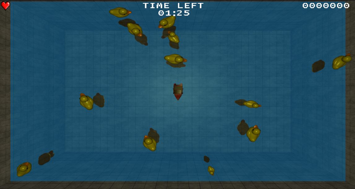
Next we consider what objects we have in the game. We can take a look at the main game screen and then list what we got.
As we can see, we have the following:
The player(s), projectiles and ducks will be represented by 3D models which are loaded from OBJ files. The particles are flat, single-colored squares. The water surface is a flat square where the water effect is rendered to a texture. The pool walls are made up of textured squares. Finally the HUD consists of 2D text and images.
We will be using a "Scene" object for rendering which is basically a container for all objects that are currently in the scene (the scene being everything visible to the player). We also want to be able to use the Scene to draw everything, making it our single point of entry for rendering. No rendering of what is visible in a scene should take place outside of the "Scene" object. This makes it easy to maintain and understand what will be seen by the player
The 3D model of the game is a static 3D model that will support basic lighting (ambient, diffuse and specular) and texture mapping. We also want to be able to describe a model-to-world space transformation for our model which includes translation, scaling and rotation of the model. Since the model-to-world information is specific to the entity it represent and not the model itself, this information is passed to the rendering call rather than being stored with the model.
#ifndef MODEL3D_H
#define MODEL3D_H


// Fwds
struct RenderStateModel3D;

class Model3d
{
	public:
	Model3d();
	~Model3d();

	void	Build(const char *modelPath);
	void	SetTexture(GLuint texture);
	void	Render(const RenderStateModel3D& renderState, const glm::mat4 &projection,
					const glm::mat4 &view, const glm::vec3 &pos, const glm::vec3 &rot, const glm::vec3 &scale);

	static void InitModel3d();
	static void PrepareRender();
	static void AfterRender();

	private:

	// BOs containing vertex and normal data for the model
	GLuint	m_vertexBuffer;
	GLuint	m_uvCoords;
	GLuint	m_normalBuffer;

	// Texture of the model
	GLuint		m_texture;

	unsigned int	m_vertexBufferSize;

	// Shader handles
	struct shaderProgramHandles
	{
		GLuint m_programID;
		GLuint m_lightPos_worldspaceID;
		GLuint m_viewMatrixID;
		GLuint m_modelViewProjectionID;
		GLuint m_modelMatrixID;
		GLuint m_modelViewMatrixID;
		GLuint m_normalMatrixID;
		GLuint m_userClipPlane0ID;

		GLuint m_lightColorID;

		GLuint m_textureID;
	};

	static shaderProgramHandles m_model3DShaderHandles;

	// If true, BOs have been built
	bool			m_built;
};

#endif
The Model3D class implements a Build function, which will load the OBJ file and create three buffer objects, then fill them with vertex, texture-coordinate and normal data. You can also set a specific texture that will be the same for all instances of the model. There is also Prepare/After-Render functions. These set some of the OpenGL states common for all Model3D objects.
This object also support basic lighting. In order for the lighting to work for the Model3d, it has its own vertex and fragment shaders where we calculate the final color. This next section will describe the lighting in more detail, so if your interested in how that part works then read on. You can skip ahead too, if you dont want to dig into the details or come back to it later. If you want to skip to the next section of rendering, head to the bottom part of the page.
The lighting model consist of three components: ambient, diffuse and specular. Bellow is an illustration of the 3 components and the final composition of all of them(Ambient, Diffuse, Specular, Combined)

Ambient

A constant, static light. If your scene takes place outside in the daytime, this would be the sun. This component is calculated in the fragment shader. In our case the ambient color is a weak white light (0.1, 0.1, 0.1).
Applying the ambient light is trivial - we use the color at the texture map (texture( textureSampler, UV ).r, texture( textureSampler, UV ).g, texture( textureSampler, UV ).b) and we multiply it with our ambient light (0.1, 0.1, 0.1)
uniform sampler2D textureSampler;

void main()
{
	vec3 albedoColor = vec3(texture( textureSampler, UV ).r, texture( textureSampler, UV ).g, texture( textureSampler, UV ).b);

	vec3 materialAmbientColor = vec3(0.1, 0.1, 0.1) * albedoColor;
Diffuse
This light is based on the idea of diffuse reflection of rough surfaces. Diffuse reflection over a rough surface will reflect the incoming light seemingly randomly due to roughness of the surface (imagine an asphalt road for example). For a more in depth explanation of the subject, I could recommend this site.
To simulate this, we are using something called "Lambert's cosine law" (Use in computer graphics) to calculate the diffuse color intensity. This will let us create a nice looking lighting effect, kind of the bread and butter of our lighting model. To do this, we will need the surface normal as well as a light direction from the light to the surface point.
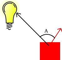
In the picture above, the bulb represents our point light and the red arrow the normal of the surface. In our game we are using a point light so we will also take into account the distance to our light. As objects move further away from the point light, the light intensity wears off. This wear-off effect is called attenuation which we model according to the Inverse-square law, which says that the intensity fall of is the distance (from light source to object) squared.
So how do we make all this come together? Well, we got the normals from reading the OBJ file. So all we need to do is calculate the light direction and the distance using our vertex and fragment shaders.
Lets start by having a look at the vertex shader
// Input vertex data
layout(location = 0) in vec3 vertexPosition_modelspace;
layout(location = 1) in vec3 vertexNormal_modelspace;
layout(location = 2) in vec2 vertexUV;

out vec3 position_worldspace;
out vec3 normal_cameraspace;
out vec3 lightDirection_cameraspace;
out vec2 UV;

uniform vec3 lightPosition_worldspace;
uniform mat4 V; // View
uniform mat4 M; // Model
uniform mat4 MV; // ModelView
uniform mat4 NM; // Normal Matrix, the transpose inverse of the ModelView matrix

void main()
{
    // Position of the vertex in worldspace
    position_worldspace = (M * vec4(vertexPosition_modelspace,1)).xyz;

    vec3 vertexPosition_cameraspace = ( MV * vec4(vertexPosition_modelspace,1)).xyz;

    vec3 lightPosition_cameraspace = ( V * vec4(lightPosition_worldspace,1)).xyz;
    lightDirection_cameraspace = lightPosition_cameraspace - vertexPosition_cameraspace;

    normal_cameraspace = mat3(NM) * vertexNormal_modelspace;

    UV = vertexUV;
}
There are a few parameters left out from the vertex shader: out float gl_ClipDistance[1] and uniform vec4 userClipPlane0. These are used to specify a clipping plane, which we only do when we render the water reflection texture. When we are not rendering the water reflection texture, and no clip plane is enabled, the value in gl_ClipDistance is simply ignored. So this part of the vertex shader has no bearing on what goes on when we are not rendering the reflection texture, hence we will not go into details on that here
The vertex shader takes a couple of in data:
And it will output the following data for the fragment shader:
Why are all the matrices being passed on instead of calculated in the shader? - Good question. The reason why all these are sent in to the shader instead of not just the simple ones (Model, View, Projection) is that it would be very heavy for the GPU to have to calculate this. Remember that the vertex shader will be called upon for EVERY vertex that is being processed. These matrices dose'nt change from vertex to vertex so its a huge waste calculating them in here.
The math is straightforward. To calculate the distance (light - fragment position) we calculate position_worldspace - the vertex position in world space (we will ofcourse also calculate the model-view-projection transformed vertex position but that is not needed for the lighting). We already have the lights position in worldspace - lightPosition_worldspace.
We still need the normal and the lights direction to calculate the intensity. We of course need the normal and the light to be transformed to the same space (if we applied the view matrix to the normal, we need to apply the view matrix to the light direction too.) In our case, we use the camera space. The reason why is because we later on will be calculating the specular component, where using the view space will make it a bit easier for us.
There is one matrix that might stand out here and that is the Normal Matix (NM). Why would we even need to try and transform the normal? It's just an orientation and should not change no matter what we do with the Model matrix, right? Well, almost. The exception is non-uniform scaling. If you scale your model 2x on the X-axis and leave the Y and Z axis at 1x, giving the model a stretched out look along the X-axis, your normals will not be correct any more. Well, cant we just apply the ModelView matrix to the normals, getting the scaling that we want? Well, we can but it wont end up with the result we want. This scaling will not make sure that perpendicularity is preserved, which is exactly what we need for a normal. In order to achieve this, we need a normal matrix. If your interested in how the normal matrix is built, I would recommend reading this article
The normal_cameraspace is simply a transformation from model-space to camera space (view space). To calculate the light direction we first transform lightPosition_worldspace to camera space (no need for a model-space to world-space transformation because the light position is already expressed in world space), then we simply subtract the lights position from the vertex position.
Lets move over to the fragment shader
in vec3 position_worldspace;
in vec3 normal_cameraspace;
in vec3 lightDirection_cameraspace;
in vec2 UV;

uniform sampler2D textureSampler;

uniform vec3 lightPosition_worldspace;
uniform vec3 lightColor;


// Ouput data
out vec3 color;

void main()
{
    vec3 albedoColor = vec3(texture( textureSampler, UV ).r, texture( textureSampler, UV ).g, texture( textureSampler, UV ).b);

    float lightPower = 50.0f;

    float distance = length( lightPosition_worldspace - position_worldspace );
    vec3 n = normalize( normal_cameraspace );
    vec3 l = normalize( lightDirection_cameraspace );
    float cosTheta = clamp( dot( n,l ), 0,1 );

	color = materialAmbientColor +
			albedoColor * lightColor * lightPower * cosTheta / (distance*distance);
}
All we need to do is to normalize the vectors and calculate the cosine of the angle between the fragment normal and the light normal. This is achieved using the dot product. We need to clamp the value between 0 and 1. Why? Because if the light is behind the fragment, the dot product will be negative. We never want that. That is it for the diffuse part, so lets move on over to the specular part.
Specular
This light is based on the idea of "specular reflection", and especially on the law of reflection. Specular reflection is what gives shiny metals their charactaristic look and something that gives a clear visual cue of the position of the light relative to the object receiving. The specular component also uses a "shininess" factor, as suggested in Phong shading
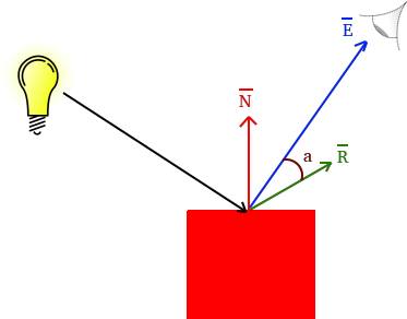
The light intensity from the specular component is similiar to that of the diffuse. The difference is that here, we compare the angle (a in the picture) between the "eye" vector (E in the picture) and the reflected light vector (R in the picture). We also apply a "shininess" factor to this light intensity by raising it the power of some value we choose (5 in our example). The higher the shininess factor, the more focused of the specular component becomes. This is not based on some physical theory but choosen to something that looks good (page 5, under section The Shading Function Model
We handle the specular light by using a vertex and fragment shader as well, lets dive right into it starting with the vertex shader
// Input vertex data
layout(location = 0) in vec3 vertexPosition_modelspace;
layout(location = 1) in vec3 vertexNormal_modelspace;
layout(location = 2) in vec2 vertexUV;

out vec3 position_worldspace;
out vec3 normal_cameraspace;
out vec3 lightDirection_cameraspace;

uniform vec3 lightPosition_worldspace;
uniform mat4 V; // View
uniform mat4 M; // Model
uniform mat4 MV; // ModelView
uniform mat4 NM; // Normal Matrix, the transpose inverse of the ModelView matrix

void main()
{
    // Position of the vertex in worldspace
    position_worldspace = (M * vec4(vertexPosition_modelspace,1)).xyz;

    vec3 vertexPosition_cameraspace = ( MV * vec4(vertexPosition_modelspace,1)).xyz;

    vec3 cameraPosition = vec3(0,0,0); // OpenGLs camera position is always fixed at 0,0,0 looking down the negativite Z axis.
    eyeDirection_cameraspace = cameraPosition - vertexPosition_cameraspace;

    vec3 lightPosition_cameraspace = ( V * vec4(lightPosition_worldspace,1)).xyz;
    lightDirection_cameraspace = lightPosition_cameraspace - vertexPosition_cameraspace;

    normal_cameraspace = mat3(NM) * vertexNormal_modelspace;

    UV = vertexUV;
}
We calculate position_worldspace the same way as for diffuse, we still need it for the attenuation (larger distance from light, weaker light)
eyeDirection_cameraspace is the E vector in the picture, it will go from the camera position straight to the vertex. Here we see the reason why we choose to use cameraspace (as mentioned before in the diffuse section), the camera in OpenGL will always be located at (0,0,0).
lightDirection_cameraspace is the vector from the light to the vertex. We will need to invert this vector in the fragment shader for the specular light (we need both though, so we calculate it this way here for the diffuse part).
normal_cameraspace here we transform the normal to camera space, same thing as we did for the diffuse part
Ok, so lets move on to the fragment shader
in vec3 position_worldspace;
in vec3 normal_cameraspace;
in vec3 lightDirection_cameraspace;
in vec3 eyeDirection_cameraspace;

uniform sampler2D textureSampler;

uniform vec3 lightPosition_worldspace;
uniform vec3 lightColor;


// Ouput data
out vec3 color;

void main()
{
    vec3 albedoColor = vec3(texture( textureSampler, UV ).r, texture( textureSampler, UV ).g, texture( textureSampler, UV ).b);

    float lightPower = 50.0f;

    float distance = length( lightPosition_worldspace - position_worldspace );
    vec3 n = normalize( normal_cameraspace );
    vec3 l = normalize( lightDirection_cameraspace );

    vec3 E = normalize(eyeDirection_cameraspace);
    vec3 R = reflect(-l,n);
    float cosAlpha = clamp( dot( E,R ), 0,1 );

    color = albedoColor * lightColor * lightPower * pow(cosAlpha,5) / (distance*distance);
}
The difference from the diffuse part here is that we also calculate E (same vector as in picture above, the eye direction) and normalize it. Then we calculate the reflection vector R (same as in picture) by using the reflect function. Note how we inverted the light direction - we need the light vector from the light to the fragment position here. Next, we calculate the intensity using lamberts law again, but this time looking at the angle between E and R, which we put into cosAlpha. Remember the "shininess" factor that we discussed above? that is why we raise cosAlpha to a factor 5 when calculating color. You can experiment with this factor, a higher value will give you a smaller but more focused specular effect.
Putting it all together
We still need to put all these components together. Bellow is the full vertex and fragment shader showing how it all fits together
Vertex shader
#version 330 core

// Input vertex data
layout(location = 0) in vec3 vertexPosition_modelspace;
layout(location = 1) in vec3 vertexNormal_modelspace;
layout(location = 2) in vec2 vertexUV;

out float gl_ClipDistance[1];

out vec3 position_worldspace;
out vec3 normal_cameraspace;
out vec3 eyeDirection_cameraspace;
out vec3 lightDirection_cameraspace;
out vec2 UV;


uniform mat4 MVP; // ModelViewProjection
uniform mat4 V; // View
uniform mat4 M; // Model
uniform mat4 MV; // ModelView
uniform mat4 NM; // Normal Matrix, the transpose inverse of the ModelView matrix
uniform vec3 lightPosition_worldspace;
uniform vec4 userClipPlane0; // user defined clip plane in view-space

void main()
{
	gl_Position =  MVP * vec4(vertexPosition_modelspace,1);

	// Calculate data needed for lighing in fragment shader
	vec3 vertexPosition_cameraspace = ( MV * vec4(vertexPosition_modelspace,1)).xyz;

	// Position of the vertex in worldspace
	position_worldspace = (M * vec4(vertexPosition_modelspace,1)).xyz;

	// Need homogenus space location for the clipping
	vec4 position_worldspaceVec4 = vec4(position_worldspace.x, position_worldspace.y, position_worldspace.z, 1);

	gl_ClipDistance[0] = dot(position_worldspaceVec4, userClipPlane0);

	vec3 cameraPosition = vec3(0,0,0); // OpenGLs camera position is always fixed at 0,0,0 looking down the negativite Z axis.
	eyeDirection_cameraspace = cameraPosition - vertexPosition_cameraspace;

	vec3 lightPosition_cameraspace = ( V * vec4(lightPosition_worldspace,1)).xyz;
	lightDirection_cameraspace = lightPosition_cameraspace - vertexPosition_cameraspace;

	normal_cameraspace = mat3(NM) * vertexNormal_modelspace;

	UV = vertexUV;
}
Fragment shader
#version 330 core

// Interpolated values from the vertex shaders
in vec3 position_worldspace;
in vec3 normal_cameraspace;
in vec3 eyeDirection_cameraspace;
in vec3 lightDirection_cameraspace;
in vec2 UV;

uniform sampler2D textureSampler;

uniform vec3 lightPosition_worldspace;
uniform vec3 lightColor;

// Output data
out vec3 color;

void main()
{
	vec3 albedoColor = vec3(texture( textureSampler, UV ).r, texture( textureSampler, UV ).g, texture( textureSampler, UV ).b);

	// Light emission properties
	float lightPower = 50.0f;

	// Material properties
	vec3 materialAmbientColor = vec3(0.1, 0.1, 0.1) * albedoColor;

	// Distance to the light
	float distance = length( lightPosition_worldspace - position_worldspace );

	vec3 n = normalize( normal_cameraspace );
	vec3 l = normalize( lightDirection_cameraspace );
	float cosTheta = clamp( dot( n,l ), 0,1 );

	vec3 E = normalize(eyeDirection_cameraspace);
	vec3 R = reflect(-l,n);
	float cosAlpha = clamp( dot( E,R ), 0,1 );

	// Put together output color from the ambient, diffuse and specular components
	color = materialAmbientColor +
			albedoColor * lightColor * lightPower * cosTheta / (distance*distance) +
			albedoColor * lightPower * pow(cosAlpha,32) / (distance*distance);
}
There should be no surprises in the code above, it is simply the three components put together at the end.
To calculate the color reflecting (what the player will see) from the light hitting the object, we want to modulate the color of the object with the incoming color of the light. So if the light is white, and the color of the object is red, we get a visible red color on the screen(the blue and green light which is part of the white light is simply absorbed by the object and wont be seen). This is achieved by multiplying the light with the material color. If the material color is pure red (1, 0, 0), it is obvious that a pure blue light (0, 0, 1) will result in no reflection of the blue light if we multiply the light color with the material color.
The ambient color part comes from a weak white light which is then multiplied with the material color and stored in materialAmbientColor.
The diffuse and specular light comes from our light source and is the result of albedoColor * lightColor * an intensity calculated for the diffuse/specular part
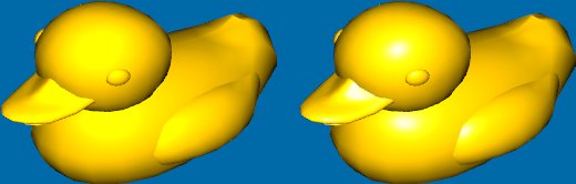
Gouraud shading - Phong shading

That is pretty much it for the lighting model. There is one more thing that is worth mentioning - the difference between Gouraud shading(image on left side) and Phong shading(image on the right side). Phong shading of the specular component is done per-pixel, where as Gouraud shading is done per vertex. Gourad shading tends to produce poor looking results on low-poly count models in comparison with Phong shading and this is because the specular lighting is not calculated per pixel but rather per vertex and then interpolated across the triangle.
Interpolated vertex values from the rasterization step
An important thing to note is that in the OpenGL graphics pipeline, the "in" values for the fragment shader will be interpolated values coming from the "out" data in the vertex shader. So, for example, our eyeDirection_cameraspace which is using the vertexPosition_modelspace will be the interpolated value at the current fragment we are calculating our specular intensity for, the eyeDirection_cameraspace will be a vector from the 3D position of the fragment to the camera. This interpolation happens at the rasterization step, right before we get to the Fragment Shader.
An improvement on the specular light
While this is an old and very basic way of lighting, we can make a small improvement to the specular highlights. All our 3D models - ducks, player and projectiles - are all made of plastic materials. These are called dielectrics and they reflect color in a different way than conductive materials (metallic objects). Non-metallic objects tend to have specular reflection where the incoming light is not colored by the material itself but purely reflect the lights color where as a metallic object would tint the light (This is mentioned for example here, under section "Metals vs Non Metals".)
By simply altering the fragment shader a bit, we can get a bit better looking highlights:
// Put together output color from the ambient, diffuse and specular components
color = materialAmbientColor +
        albedoColor * lightColor * lightPower * cosTheta / (distance*distance) +
        lightPower * pow(cosAlpha,32) / (distance*distance);
Its a subtle, but nice improvement that you can try out yourself. This suggestion came from Kostas Anagnostou who has very kindly offered tips and suggestions on some of my writing.